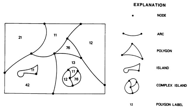
Figure l.--Topological elements of a polygon map.
First printing, 1986
Second printing, 1990
Converted to HTML by Ben Discoe, 1998
The Earth Science Information Centers (ESIC) distribute digital cartographic/geographic data files produced by the U.S. Geological Survey (USGS) as part of the National Mapping Program. The data files are grouped into four basic types. The first type, called a Digital Line Graph (DLG), is line map information in digital form. These data files include information on planimetric base categories, such as transportation, hydrography, and boundaries. The second type, called a Digital Elevation Model (DEM), consists of a sampled array of elevations for ground positions that are usually at regularly spaced intervals. The third type, Land Use and Land Cover digital data, provide information on nine major classes of land use such as urban, agricultural, or forest as well as associated map data such as political units and Federal land ownership. The fourth type, the Geographic Names Information System, provides primary information for known places, features, and areas in the United States identified by a proper name.
The digital cartographic data files from selected quadrangles currently available from ESIC include the following:
The data may be used in the production of cartographic products, such as plotting base maps, and for various kinds of spatial analysis. The data also may be combined with other geographically referenced data for automated analyses in support of various decision making processes.
Any use of trade, product, or firm names in this publication is for descriptive purposes only and does not imply endorsement by the U.S. Government. Manuscript approved for publication September 26, 1986. This document describes the Land Use and Land Cover digital data prepared from 1:250,000- or 1:100,000-scale Land Use and Land Cover and associated maps. This program will eventually result in complete national coverage.
The set of Land Use and Land Cover and associated maps consists of Land Use and Land Cover, political units, hydrologic units, census county subdivisions, Federal land ownership, and State land ownership (optional).
The Land Use and Land Cover map is compiled to portray the Level II categories of the Land Use and Land Cover classification system documented by Anderson and others (l976). The Level II categories of this Land Use and Land Cover classification system provide the user with a basic framework to which third- and fourth-level categories may be added.
The associated maps portray either natural or administrative information. They provide the user with the opportunity to utilize the Land Use and Land Cover maps and data, either individually or collectively, to produce graphic or tabular data for the areas portrayed on the associated maps. This mapping system is constructed in such a way that the Land Use and Land Cover data can be related to other resource fields such as soils, geology, hydrology, and demography.
To provide the data in digital form, the Geographic Information Retrieval and Analysis System (GIRAS) has been developed (Mitchell and others, l977). The data structure used in GIRAS to store the information is the result of a series of evolving structures and, as such, reflects the judgment by the USGS concerning the presentation and format of polygonal data. For those users better able to handle data in a grid cell form, data are also provided in a Composite Theme Grid (CTG) format.
The characteristics of the digital cartographic data base for Land Use and Land Cover and associated maps reflect the parameters used in compiling the maps. The Land Use and Land Cover mapping program is designed so that standard topographic maps at a scale of l:250,000 can be used as a base for compilation and reproduction. In a few cases, USGS has prepared Land Use and Land Cover and associated maps at a scale of 1:100,000 when the 1:100,000-scale topographic map base was available.
The l:250,000-scale mapping format is usually a quadrangle unit of l° of latitude x 2° of longitude. The 1:100,000-scale mapping format has been established as a 30' x 60' quadrangle, normally a quarter of a 1:250,000-scale quadrangle. Both series are based on the Universal Transverse Mercator projection.
Land Use and Land Cover maps provide data to be used either by themselves or in combination with the other data sets produced in the program. The basic sources of land use compilation data are NASA high-altitude aerial photographs, and National High-Altitude Photography (NHAP) program photographs, usually at scales smaller than l:60,000. The l:250,000-scale topographic map series is generally used as the base map for the compilation of the Land Use and Land Cover maps and the associated overlays; 1:100,000-scale topographic map bases have been used on rare occasions. Although compilation of Land Use and Land Cover data is performed on a film-positive base usually enlarged to a scale of approximately l:l25,000, the associated overlays are both compiled and digitized at a scale of l:250,000.
Land Use and Land Cover data compilation is based upon the classification system and definitions of Level II Land Use and Land Cover shown in table 1. All features are delineated by curved or straight lines that depict the actual boundaries of the areas (polygons) being described. The minimum size of polygons depicting all Urban or Built-up Land (categories 11-17), Water (51-54), Confined Feeding Operations (23), Other Agricultural Land (24), Strip Mines, Quarries, and Gravel Pits (75) and urban Transitional areas (76), is 4 hectares (ha). All other categories of Land Use and Land Cover have a minimum polygon size of 16 ha. (Those sizes also are considered the minimum sizes to which polygons are digitized.) In the Urban or Built-up Land and Water categories, the minimum width of a feature to be shown is 200 m; (that is, if a square with sides 200 m in length is delineated, the area will be 4 ha). Although the minimum-width consideration precludes the delineation of very narrow and very long 4-ha polygons, triangles or other polygons are acceptable if the base of the triangle or minimum width of the polygon is 200 m in length and if the area of the polygon is 4 ha. Exceptions to this specification are limited access highways (14) and all double line rivers (51) on the 1:250,000-scale base which shall have a minimum width of 92 m. For categories other than Urban or Built-up Land and Water, the 16-ha minimum size for delineation requires a minimum-width polygon of 400 m. Line weight for delineating Land Use and Land Cover polygons and for neatlines is 0.l0 mm at the production scale of l:250,000.
The political unit map provides a graphic portrayal of county, independent city, and State boundaries and numerical codes and is compiled on a base map at a scale of either 1:250,000 or 1:100,000. Source materials for political unit map boundaries are the 1:250,000- or 1:100,000-scale base map and the 1970 Bureau of the Census unpublished maps entitled "County Subdivisions-- Townships and Places" or 1980 County Subdivision Maps (U.S. Bureau of the Census, 1983e). State and county political units (including independent cities in Maryland, Missouri, Nevada, and Virginia) are encoded with a five-digit number in accordance with the 1970 Geographic Identification Code Scheme (U.S. Bureau of the Census, 1972b) or 1980 Geographic Identification Code Scheme (U.S. Bureau of the Census, 1983f) and the County and City Data Book (U.S. Bureau of the Census, 1972a) or County and City Data Book (U.S. Bureau of the Census, 1983d).
The census county subdivision map depicts boundaries and numerical codes for either census tracts in Standard Metropolitan Statistical Area (SMSA) counties before June 1983, Metropolitan or Primary Metropolitan Statistical Area (MSA/PMSA) counties since June 1983, or minor civil divisions (or equivalent divisions) in non-SMSA/MSA/PMSA counties. Boundaries and codes for census tracts in SMSA counties are based on map data in Census Tracts reports (U.S. Bureau of the Census, 1972) or on the Census Tracts maps (U.S. Bureau of the Census, 1983c). Boundaries for minor civil divisions are from the 1970 Bureau of the Census unpublished maps entitled "County Subdivisions--Townships and Places" or 1980 County Subdivision Maps (U.S. Bureau of the Census, 1983e). Each SMSA/MSA/PMSA is encoded with a four-digit number and each census tract is encoded with a one-to four-digit number, with a possible two-digit number extension, that is unique for each census tract within a given SMSA/MSA. Minor civil divisions are encoded with an eight-digit number in accordance with the 1970 Geographic Identification Code Scheme (U.S. Bureau of the Census, 1972b) or 1980 Geographic Identification Code Scheme (U.S. Bureau of the Census, 1983f): the first two digits are the State code, the next three are the county code, and the last three are the minor civil division identifier.
Table l.--U.S. Geological Survey Land Use and Land Cover Classification System for Use with Remote Sensor Data
| LEVEL 1 | LEVEL II |
|---|---|
| 1 Urban or Built-up Land | 11 Residential |
| 12 Commercial and Services | |
| 13 Industrial | |
| 14 Transportation, Communications and Utilities | |
| 15 Industrial and Commercial Complexes | |
| 16 Mixed Urban or Built-up Land | |
| 17 Other Urban or Built-up Land | |
| 2 Agricultural Land | 21 Cropland and Pasture |
| 22 Orchards, Groves, Vineyards, Nurseries, and Ornamental Horticultural Areas |
|
| 23 Confined Feeding Operations | |
| 24 Other Agricultural Land | |
| 3 Rangeland | 31 Herbaceous Rangeland |
| 32 Shrub and Brush Rangeland | |
| 33 Mixed Rangeland | |
| 4 Forest Land | 41 Deciduous Forest Land |
| 42 Evergreen Forest Land | |
| 43 Mixed Forest Land | |
| 5 Water | 51 Streams and Canals |
| 52 Lakes | |
| 53 Reservoirs | |
| 54 Bays and Estuaries | |
| 6 Wetland | 61 Forested Wetland |
| 62 Nonforested Wetland | |
| 7 Barren Land | 71 Dry Salt Flats |
| 72 Beaches | |
| 73 Sandy Areas Other than Beaches | |
| 74 Bare Exposed Rock | |
| 75 Strip Mines, Quarries, and Gravel Pits | |
| 76 Transitional Areas | |
| 77 Mixed Barren Land | |
| 8 Tundra | 81 Shrub and Brush Tundra |
| 82 Herbaceous Tundra | |
| 83 Bare Ground | |
| 84 Wet Tundra 85 Mixed Tundra | |
| 9 Perennial Snow or Ice | 91 Perennial Snowfields |
| 92 Glaciers |
The hydrologic unit map is based on the Hydrologic Unit Maps published by the USGS Office of Water Data Coordination, together with the list "Boundary descriptions and name of region, sub- region, accounting units, and cataloging unit" or USGS Circular 878-A, Codes for the Identification of Hydrologic Units in the United States and the Caribbean Outlying Areas (U.S. Geological Survey, 1982). The hydrologic units are encoded with an eight-digit number that indicates the hydrologic region (first two digits), hydrologic subregion (second two digits), accounting unit (third two digits), and cataloging unit (fourth two digits).
The USGS has the responsibility for researching, obtaining, and formatting maps, plots, and other descriptive data related to Federal land ownership. Minimum size for the delineation is l6 ha. Ownership is encoded according to the agencies listed in table 2.
Table 2.--Federal Land Ownership
| Code | Agency |
| DEPARTMENT OF AGRICULTURE | |
| 11 | Agricultural Research Service |
| 12 | Forest Service (National Forest) |
| 13 | Forest Service (National Grassland) |
| DEPARTMENT OF COMMERCE | |
| 21 | National Oceanic and Atmospheric Administration |
| DEPARTMENT OF DEFENSE | |
| 31 | Air Force |
| 32 | Army |
| 33 | Army (Corps of Engineers - Civil Works) |
| 34 | Navy |
| DEPARTMENT OF THE INTERIOR | |
| 41 | Bonneville Power Administration |
| 42 | Bureau of Indian Affairs (does not include Indian lands held in trust) |
| 43 | Bureau of Land Management |
| 44 | Bureau of Mines |
| 45 | Bureau of Reclamation |
| 46 | Fish and Wildlife Service (National Wildlife Refuge) |
| 47 | National Park Service (National Monument, Seashore, and Recreation Area) |
| 48 | National Park Service (National Park) |
| DEPARTMENT OF JUSTICE | |
| 51 | Bureau of Prisons |
| DEPARTMENT OF STATE | |
| 61 | International Boundary and Water Commission, U.S. and Mexico |
| DEPARTMENT OF TRANSPORTATION | |
| 71 | Federal Aviation Administration |
| 72 | Federal Railroad Administration |
| 73 | U.S. Coast Guard |
| OTHER AGENCIES | |
| 81 | Energy Research and Development Administration |
| 82 | General Services Administration |
| 83 | National Aeronautics and Space Administration |
| 84 | Tennessee Valley Authority |
| 85 | Veteran's Administration |
In instances in which the USGS has a cost-sharing cooperative agreement with a specific State, a map overlay showing an inventory of State-owned land is produced from data furnished by the State. This overlay is compiled on the same map base used for the other overlays. The polygons are encoded according to the referencing system used by the State.
The GIRAS digital data structure was designed to handle large quantities of map data of the polygon type. The topological elements associated with polygon maps are shown in figure 1. A polygon is an area that is homogeneous in the characteristic (for example, Land Use and Land Cover) being mapped. An arc describes a boundary either between two polygons or between a polygon and the outside of the map. Further defined, an arc begins at one node, or point common to three or more arcs (that is, an intersection), and ends at another node but does not pass through any node. A special case is a simple island polygon totally surrounded by a larger polygon. For purposes of digitizing, an arbitrary point on the boundary of the island is chosen as the beginning and ending node of the arc. In the GIRAS structure, the common boundaries, or arcs, are digitized only once. The arcs are then linked together by editing software to form polygons.
Figure l.--Topological elements of a polygon map.
Each polygon label on the map is an integer code, not necessarily unique, that identifies or describes the polygon in which it is placed or to which it points. Note that the GIRAS format has one and only one 4-byte attribute code associated with each polygon. As a rule, each GIRAS polygon attribute is a direct copy of a polygon label from the source Land Use and Land Cover or associated map overlay. There are three exceptions to this rule: (1) an attribute code of zero (0) is associated with the outside of the map; (2) special attribute codes are associated with the unlabeled polygons (see page 23 and table 5); and (3) attributes for census tracts are all 10-digit codes, of the form "laaattttss," where "l" is always the first digit and is an indication that the code is for a census tract rather than a minor civil division, "aaa" are the first three digits of the SMSA number (the fourth digit is assumed to be zero), "tttt" is the tract number (justified with leading zeros), and "ss" is the two-digit split tract extension, if any, or "00" if there is no extension.
Within the GIRAS data structure, the basic topological elements of a polygon map (arcs, nodes, and polygons) are all uniquely identified and cross-referenced to one another. The spatial location of an arc is given by a string of x,y points; the first point is its beginning (from) node, and the last point is its ending (to) node. The sequence of points of an arc defines a direction that, since the arc separates two polygons, determines a polygon to the right and a polygon to the left. A single node is the end-point (first and (or) last) of three or more arcs (or the first and last end-point of a one-arc island). A given polygon is spatially defined as the sequence of arcs that constitute its boundary, both external perimeter and any internal islands.
The data capture procedure involves the conversion of the source material into a digital format. As defined by GIRAS, the digitization process includes not only the initial conversion to digital form, but also the editing process by which clean or logically correct data files are produced.
In digitizing, lines are not tagged in any way, and all that is required is the capability to recognize line intersections (nodes) during computer processing. Since Land Use and Land Cover maps consist entirely of polygons, the map is completely defined when each arc, including the arcs that are the boundaries of the map, has been digitized. Along with the line data, a file that contains at least one attribute and a point inside the polygon (represented by an x,y coordinate pair) for each polygon of the map must be entered into the system. These data are not in the GIRAS format at the end of the digitizing process. Data are converted to the GIRAS format only when editing is finished.
After the necessary data have been captured, the following steps are used to produce a GIRAS file:
Spatial data in the GIRAS format can be applied to individual problems through manipulation and analysis procedures such as:
The first two procedures in the list deal with coordinate conversion. To apply the data to needs of various users, it is often necessary to be able to rotate and translate the coordinate system and scale it to the desired size. Similarly, a facility to transform the data to another map projection is desirable, particularly when supplemental data exist on a different projection.
A number of existing data systems utilize data stored in grid cells. Thus, the ability to convert the polygon structure to a grid-cell format can be very useful.
The Land Use and Land Cover and associated map data files are converted to grid cells of a specific size and orientation to permit their addition to an existing data base. This permits GIRAS data to be used where the GIRAS data structure is inappropriate. GIRAS's capability to produce data in both polygon and grid-cell formats provides a flexibility whereby the needs of more users can be met.
Area summaries for a GIRAS data set may be obtained directly from the file. However, if a further breakdown of the information (for example, land use within each political unit for a data set) is wanted, it may be derived more easily from grid-cell formatted information than from an arc-segment file. Once all associated maps as well as the Land Use and Land Cover map for a 1:250,000-scale quadrangle sheet are in GIRAS format, they may be converted to one file of grid-cell information (an explanation of the CTG data file format begins on page 25) from which the more detailed summary described above may be obtained. For example, with the grid-cell (CTG) file, summaries of Land Use and Land Cover by county within a given drainage basin can be produced.
As with the grid-cell format data, the GIRAS format data facilitate production of certain types of information. An environmental study might require that the length of the border between two noncompatible types of Land Use or Land Cover (procedure 6) be known. For example, if an area of industrial land borders a lake under study, the amount of lakeshore occupied by the industrial site might be of interest. This type of information can be derived easily from the arc-segment GIRAS files.
While GIRAS stores polygons as the arcs of which they are composed, many information systems that deal with polygon data store those polygons as complete entities. To bridge the gap between the two formats, conversion to a standard polygon format is necessary. Although this requires more storage than GIRAS's format, it allows the use of a simpler set of software for plotting, perimeter calculation, and area calculation.
Another technique for extracting information from the GIRAS files is the selection of an area smaller than the standard 1° x 2° map data file (procedure 7). It is often helpful to select data from the files for closer consideration. This windowing process reduces the amount of information handled by eliminating the portions of the map that are of no interest to the study. Once this smaller portion has been selected, any of procedures 1 through 6 may be applied.
Computer-generated graphics may be used to augment the manipulations and analyses described previously. A computer-generated shaded color plot of the Level II Land Use and Land Cover for a data set along with a summary of the land use gives the investigator a spatial perspective of the distribution of Land Use and Land Cover over the area mapped. If it would be more helpful to see only one or more of the land uses displayed, they can be specially selected. If the lengths of borders between two specific Land Uses or Land Covers are under study, a plot showing only those two Land Uses or Land Covers would be helpful.
The detailed summary of Land Use and Land Cover by county might be illustrated by placing the outline of the county over the Land Use and Land Cover map. The pattern of Land Use and Land Cover for that county can be seen with the areas of the different land uses computed and displayed.
Large sets of complex spatial data, such as those handled by GIRAS, necessitate an efficient data structure. Table 3 shows some measure of GIRAS data volumes derived from records of data editing procedures. The numbers of coordinates (two coordinates, x and y, per point) are those defining the arcs and reflect the minimum number of points needed; straight two-point line
Table 3.--Sample GIRAS data volumes from 1:250,000-scale map overlays
| Sample size | Average | Maximum | |
| Land Use and Land Cover | 239 quads: | ||
| Number of arcs | 9,434 | 31,739 | |
| Number of coordinates | 226,408 | 714,530 | |
| Number of polygons | 4,238 | 13,135 | |
| Political units | 221 quads: | ||
| Number of arcs | 48 | 143 | |
| Number of coordinates | 4,912 | 29,248 | |
| Number of polygons | 18 | 51 | |
| Census county subdivisions | 221 quads: | ||
| Number of arcs | 605 | 7,581 | |
| Number of coordinates | 18,706 | 68,386 | |
| Number of polygons | 221 | 2,793 | |
| Hydrologic units | 220 quads: | ||
| Number of arcs | 35 | 68 | |
| Number of coordinates | 7,181 | 17,428 | |
| Number of polygons | 13 | 25 | |
| Federal land ownership | 102 quads: | ||
| Number of arcs | 103 | 981 | |
| Number of coordinates | 7,847 | 62,280 | |
| Number of polygons | 69 | 636 |
segments have replaced multipoint curves within the spatial resolution tolerance of the original graphic map. The actual physical size of a GIRAS file is basically a function of the numbers of arcs (NA), coordinates (NC), and polygons (NP): approximately (90NA + 5NC + 80NP) bytes, plus identifying and descriptive data as specified in the map header and text subfile sections. The greater complexity of Land Use and Land Cover maps results in a large number of arcs and polygons recorded as compared to the number recorded for the associated maps.
As indicated earlier, Land Use and Land Cover and associated map data are available in two physical file formats, GIRAS and CTG (Composite Theme Grid). The CTG file format is explained beginning on page 25. The GIRAS file format is a specific physical implementation of the logical GIRAS data structure. The format was designed to optimize storage requirements, transfer operations, and sequential processing. A standard character-formatted (usually ASCII-coded) GIRAS file consists of fixed length 80-character (card-image) logical records. Each 80-character logical record may consist of anywhere from 1 to 16 data-element fields, depending upon where, within the file, it is located. Each data-element field may contain only one of three types of data elements: (1) a 16-bit binary integer, (2) a 32-bit binary integer, or (3) a string of text characters. Each integer is coded as one or more digits with a possible leading minus sign and leading blanks (i.e., right-justified) within a fixed field of either five characters (for 16-bit integers) or ten characters (for 32-bit integers).
In some cases a binary-formatted GIRAS file can be made available. A GIRAS binary file consists of fixed-length 32-byte (8 bits per byte) logical records. For integer data, each 32-byte GIRAS binary record is equivalent to an 80-character GIRAS card image; each 16-bit (5-digit) integer is stored in a 2-byte binary integer (two's complement notation) field, and each 32-bit (10-digit) integer is stored in a 4-byte binary integer field. Each card image record with text data is represented as two sequentially adjacent 32-byte records with EBCDIC coded characters (the last 16 characters of the card-image record are always blank). A GIRAS file, either in binary or character format, logically consists of six or more subfiles. The general structure of a GIRAS file is shown in figure 2; details are shown in figures 3-8.
The first six subfiles always exist (in the order shown in figure 2); the seventh, the text subfile, may or may not exist for data released by the Earth Science Information Center (ESIC); the eighth, the associated data subfile, is meant for user-attached data and is never present in ESIC-released data. A map data file may need to be divided spatially into several parts (sections) for processing purposes. For this reason, the second through sixth sub-files (fig. 2, B through F) may be repeated, one set of five subfiles per section. A text subfile (only one per GIRAS file) may follow the final section subfile.
A GIRAS file contains a number of different types of data elements--text, codes, identifiers, counters, pointers, and some derived measurement data. Most of these data elements will be explained under the descriptions of the various subfiles below. However, one type of data, the coordinate data, needs further explanation here. All coordinates stored within a GIRAS file are coded as 2-byte (16-bit) integers. The coordinate frame of reference is defined in the map header of the file by a projection code (MPJ, see fig. 3) and six control points. The control points usually define the 1° x 2° (for 1:250,000-scale base maps) or 30' x 1° (for 1:100,000-scale base maps) quadrangle on which the overlay data are based. The latitude and longitude values are given as positive integers of the form DDDMMSS, where DDD is degrees, MM is minutes, and SS is seconds. West longitude values are given as positive numbers, increasing in value from east to west. For each of the control points, the internal x,y coordinates are equated with the geographic (latitude and longitude) coordinates of the point. The resolution of an internal coordinate unit is indicated by the map scale (MSC) value in the map header. This value is the scale denominator of a graphic plot of the GIRAS file, if the data were plotted at one internal coordinate unit per mil (0.001 in.) on the plot.
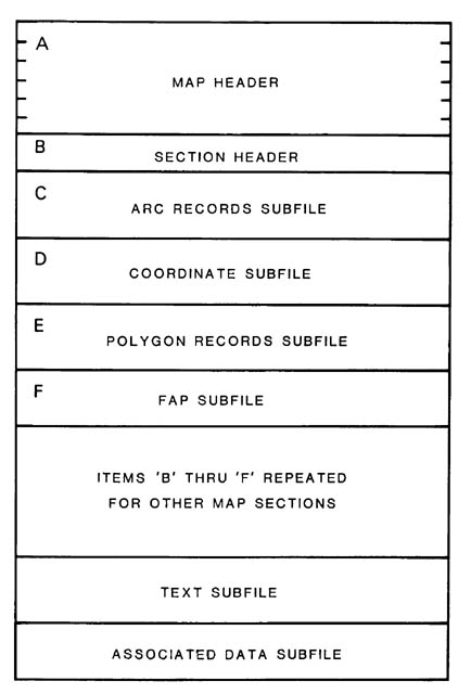
Figure 2.--GIRAS file structure.
A GIRAS file containing data based on a standard USGS 1:250,000- or 1:100,000-scale quadrangle (such as the Land Use and Land Cover and associated map series) is routinely stored in a local (to the map) UTM coordinate system (MPJ = "1" for UTM). Since 16 bits are not enough to store full UTM coordinates (which may exceed 4,000,000 m), the nearest 100,000-m UTM grid intersection, which is both west and south of all map control points, is used as a local origin (x,y = 0,0). Further, the resolution of an internal coordinate unit is set to l0 m (the MSC value = "393,701"). Using this coordinate referencing system, a GIRAS file may store data covering a 327,680-m square, more than enough for 1:250,000- and 1:100,000-scale quadrangle-based data.
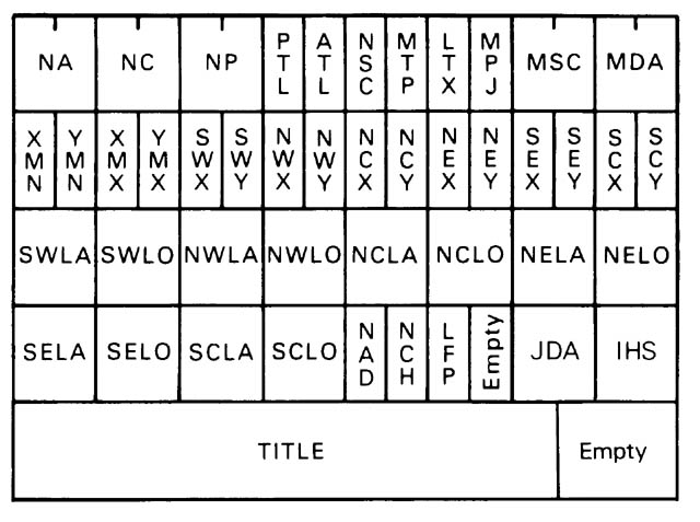
| Name | Length (digits) |
Description |
|---|---|---|
| NA | 10 | Number of arc records in map |
| NC | 10 | Number of arc coordinates in map |
| NP | 10 | Number of polygon records in map. |
| PTL | 5 | Point tolerance (in coordinate units). |
| ATL | 5 | Arc length tolerance (in coordinate units). |
| NSC | 5 | Number of map sections. |
| MTP | 5 | Map type code. |
| LTX | 5 | Length of text subfile. |
| MPJ | 5 | Map projection code. |
| MSC | 10 | Map scale denominator (1 coordinate unit per 1 mil). |
| MDA | 10 | Source map date. |
| XMN to YMX | 5 ea. | Minimum and maximum x,y coordinates for map. |
| SWX to SCY | 5 ea. | x,y coordinates of control points. |
| SWLA to SCLO | 10 ea. | Latitude and longitude of control points. |
| NAD | 5 | Number of records of associated data. |
| NCH | 5 | Number of characters in TITLE. |
| LFP | 5 | Length of FAP subfile(s). |
| JDA | 5 | Julian Date of file creation. |
| IHS | 5 | Time of file creation, in hundredths of a second. |
| TITLE | 64 | Title of up to 64 characters. |
Figure 3.--GIRAS map header.
The map header (fig. 3) contains a substantial amount of information, including the amount of data in the file, the date of the source material, title information, and ground control information. The values in variables NA, NC, NP, and LFP represent totals of the corresponding values for each section of the map data file. For example, NA is the sum of the NAS (number of arcs in a section) values for all sections of the map data file. These values can be used to estimate the length of the file before analysis. Note that since the value of LFP is stored as a 16-bit integer, LFP values exceeding 32,767 will be represented by a spurious number. The point tolerance (PTL) and arc length tolerance (ATL) are values used during processing and editing of the data to eliminate spurious or unneeded data. PTL is the width, in internal coordinate units, of a corridor that was used to delete unnecessary points from each arc of the map and reflects the relative accuracy of the digital data with respect to the original graphic lines. ATL is the minimum allowable length (in internal coordinate units) of any arc on the map. The possible map type codes (MTP) are listed in table 4.
The map date (MDA) is the year of the source material used to make the map, which is usually not the same as the year the map or data set is published. The number of characters (NCH) in the title is meant to indicate that the map title (TITLE) occupies the first NCH bytes of the final record of the map header. Because the value of NCH has been manually input and not verified, it may be spurious.
Table 4.--Map type codes for GIRAS data base
| Code | Map type |
|---|---|
| 1 | Land Use and Land Cover |
| 2 | political units |
| 4 | census county subdivisions |
| 10 | hydrologic units |
| 20 | Federal land ownership (optional) |
| 40 | State land ownership (optional) |
Because of previous computer constraints, the number of x,y coordinates (twice the number of arc points) of a section of a map data file is held to 32,000; the number of arcs, to 2,500; the number of polygons, to 1,500; and the total length of a FAP (file of arcs by polygon) subfile, to 6,000. Where these limits are exceeded within one map data file, the map area is broken into more than one section.
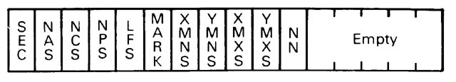
| Name | Length (digits) |
Description |
|---|---|---|
| SEC | 5 | Section number. |
| NAS | 5 | Number of arcs in section. |
| NCS | 5 | Number of arc coordinates in section. |
| NPS | 5 | Number of polygons in section. |
| LFS | 5 | Length of subfile assigning arcs to polygons. |
| MARK | 5 | Indicates processing history. |
| XMNS, YMNS | 5 ea. | Minimum x,y coordinates in section. |
| XMXS, YMXS | 5 ea. | Maximum x,y coordinates in section. |
| NN | 5 | Number of nodes in section. |
Figure 4.--GIRAS section header.
Four elements near the end of the section header (fig. 4; XMNS, YMNS, XMXS, and YMXS) are the coordinate limits of the section, and indicate the minimum and maximum x and y coordinate values within the section.
Each record of the arc records subfile (fig. 5) contains a pointer (PLC) to the x,y coordinates that represent the arc in the coordinate subfile. There is one PLC value for each arc, and it represents the position within the coordinate subfile of the last coordinate of that arc. For example, if the first arc contained 6 points (12 coordinates), its PLC value would be 12, and if the second arc contained 8 points (16 coordinates), the PLC value would be 28 (12+16). Following this pattern, the last arc would have a PLC value equal to the total number (NCS) of coordinates in the subfile. Along with the PLC value, each record in the arc records subfile contains the unique numbers (PL and PR) of the polygons that each arc separates and the attributes (PAL and PAR) of those polygons. The outside of the map or map section is referred to as polygon number "0" (zero) with attribute "0" (zero).
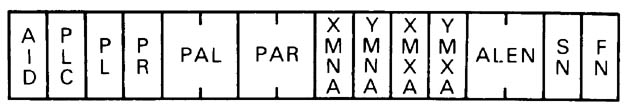
| Name | Length (digits) |
Description |
|---|---|---|
| AID | 5 | Arc number. |
| PLC | 5 | Position of last arc coordinate in COORDINATE subfile. |
| PL | 5 | Polygon number of polygon to left of arc. |
| PR | 5 | Polygon number of polygon to right of arc. |
| PAL | 10 | Attribute of polygon to left of arc. |
| PAR | 10 | Attribute of polygon to right of arc. |
| XMNA, YMNA | 5 ea. | Minimum x,y coordinates in arc. |
| XMXA, YMXA | 5 ea. | Maximum x,y coordinates in arc. |
| ALEN | 10 | Arc length in coordinate units. |
| SN | 5 | Node number at beginning of arc. |
| FN | 5 | Node number at end of arc. |
Figure 5.--A GIRAS arc record.
The coordinate subfile (fig. 6) is simply a sequential listing of every x,y coordinate needed to represent the arcs of the map section. When a map is digitized, a series of x,y coordinates is recorded for each arc of the map. Although the choice of direction taken by the digitizer during recording is not significant, that direction--once determined by digitizing--becomes important in the data structure. The direction of recording is referred to as the positive direction for the arc, and each arc can be referred to by a positive or negative representation of its arc identification number (AID). For example, if arc 1 is read from its starting node (SN) to the node (FN) at the end of the arc, it is represented as "+1" or 1. If the arc is to be read from FN to SN (in reverse order from that stored in the coordinate subfile), it may be represented by "-1." The need for this will become apparent when the FAP subfile is described.
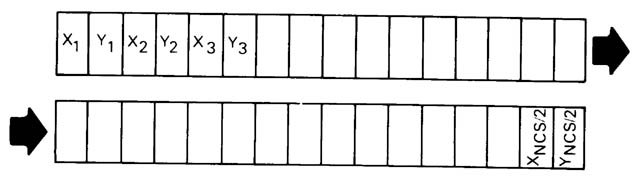
| Name | Length (digits) |
Description |
|---|---|---|
| xn | 5 | x integer coordinate value of point n |
| yn | 5 | y integer coordinate value of point n |
COORDINATE (PLC(I-1)+1) is the x coordinate value of the first point of
arc I.
[PLC(0)=0]
COORDINATE (PLC(I)) is the y coordinate value of the last point of arc I.
The order within the COORDINATE subfile of the (x,y) points of a given arc determines the direction of the arc, and therefore the right and left of the arc. The first point in an arc (x,y) string is its "FROM" or "START" node; the last point in an arc (x,y) string is its "TO" or "END" node.
LEFT From --------------------- To RIGHT |
Figure 6.--GIRAS coordinate subfile.
To repeat, the order in which the arcs are recorded is not significant, but their order, once established, is important to the GIRAS structure. The order allows each arc to be accessed by using only the unique arc number (AID) and its PLC value. No pointers to the beginning coordinate of an arc exist in the coordinate subfile. For example, if the PLC for arc 1 is 16, then the 17th element of the coordinate subfile will be the first coordinate of arc number 2. This permits storage of the x,y coordinates in the smallest possible space.
The polygon records subfile (fig. 7) describes each polygon of the map section. The polygon identification number (PID) is the unique number by which each polygon may be referenced. The PLA value (equivalent in purpose to PLC in an arc record) points to a list, in the FAP subfile, of the arcs that comprise that polygon's borders. As with the coordinate subfile (referenced by PLC), the FAP subfile is a sequential list of information. For each polygon it contains the list of the numbers (AID's) of the arcs needed to create the boundary of the polygon. These values are listed first for polygon 1, second for polygon 2, and so on for each polygon. If polygon 1 of a section were the three-sided polygon with attribute 76 in figure 1, it would be composed of three arcs, and the PLA value for it would be "3." If polygon 2 were the polygon in figure 1 labeled 42, the situation would be slightly more complex because the FAP subfile entry for this polygon must also include the arcs that make up the outside boundary of the island within polygon 2. In this case, the value of PLA would be the number of arcs it takes to enclose the polygon (4) plus one place for a zero (indicating that what follows is a list of arcs making up an island) and one place for an arc number to represent the island (2) plus the PLA of the previous polygon (3). The PLA value for polygon 2 would then be 9. It also follows that the PLA value for the last polygon will equal the total length of the FAP subfile (LFS in the section header). A detailed explanation of the FAP subfile begins on page 18.
| Name | Length (digits) |
Description |
|---|---|---|
| PID | 5 | Polygon number. |
| PLA | 5 | Position of last arc number of polygon in FAP subfile. |
| CX, CY | 5 ea. | x,y coordinates of an interior point (arbitrarily positioned). |
| ATT | 10 | Polygon attribute. |
| AREA | 10 | Area of polygon in coordinate units squared. |
| XMNP,YMNP | 5 ea. | Minimum x,y coordinates of polygon. |
| XMXP,YMXP | 5 ea. | Maximum x,y coordinates of polygon. |
| PERL | 10 | Perimeter length of polygon in coordinate units. |
| NIW | 5 | Number of islands contained within polygon. |
| NIP | 5 | Number of the polygon containing this polygon, if it is an island. |
Figure 7.--A GIRAS polygon record.
The next entries in the polygon record are the x,y coordinates (CX and CY) of a random point inside the polygon. These coordinates do not represent a centroid or center of mass. They define a point inside the boundary of the polygon that was recorded during the digitizing process and used during the editing process to tie the arcs together to form the polygon. The polygon attribute (ATT) and polygon area (AREA) also are included, as well as the minimum and maximum x and y coordinates (XMNP, YMNP, XMXP, YMXP) of the polygon. The area of a polygon is useful information and is stored to avoid recalculation. The limits of the polygon allow the user to--in a simple way--isolate a polygon from much of the rest of the map section. The perimeter length (PERL) of the polygon can be used along with the total area occupied by the polygon to compute measures of the compactness of the polygon.
The final two entries in the polygon record are the number of islands (NIW) contained within the polygon and the number (NIP) of the polygon that contains another polygon as an island. The number of islands is helpful when used along with PLA to read the island entries in the FAP subfile. The NIP entry identifies another polygon which totally surrounds the polygon. The attribute of the surrounding polygon can easily be obtained by looking at the value of ATT in the record for polygon number NIP. If the data were to be compressed and small polygons to be eliminated or combined with larger surrounding polygons, NIP would show quickly which polygon number and type that small island would become.
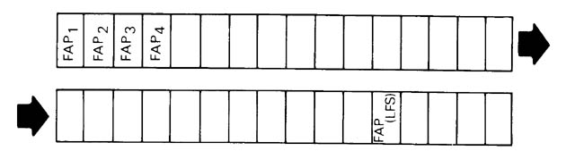
The FAP (file of arcs by polygon) subfile (fig. 8) is the last subfile that exists separately for each map section. It is accessed by way of an entry (PLA) in the polygon records subfile. The total length (LFS) of the FAP subfile is stored in the section header. To understand the contents of the FAP subfile, it is helpful to know how its contents are used to construct a polygon. The FAP subfile consists of lists of arcs, one arc-list per polygon. The arcs for a polygon with no islands
Each element contains an arc identification number pointing to the arcs that make up a specific polygon. FAP (PLA(I-1)+1) is the first arc bordering polygon I. Within the FAP subfile, the identification numbers of the arcs constituting a given polygon are ordered clockwise around the perimeter of the polygon and counterclockwise around interior islands of the polygon. A positive arc identification number indicates the polygon is to the right of the arc. A negative arc identification number indicates the polygon is to the left of the arc. A zero FAP element indicates that the arc identification numbers following it, and before the next zero in the subfile or the end of the FAP list, point to the arcs that constitute an interior island of the polygon. |
Figure 8.--GIRAS FAP subfile.
are listed in clockwise order around the polygon from an arbitrary starting point. This starting point can be either the starting node (SN) or final node (FN) of the first arc in the list. If the starting point is SN for the arc (the polygon to the right of the arc), then the number of that arc is recorded in FAP as "+AID" or "AID." If the starting point is FN (the polygon is to the left of the arc), then that arc is recorded as "-AID." In figure 9, the direction in which the arcs of a polygon were digitized (positive direction) is indicated by the filled arrows. The list of arcs composing the polygon begins at the node closest to the internal point (CX, CY), and the FAP entry for this polygon is "-l 4 3 -2."
Figure 9.--GIRAS FAP subfile creation.
The FAP subfile contains a series of elements for each polygon whether or not that polygon is an island. If the polygon is an island, a list of the arcs that make up its outside boundary will also be listed in counterclockwise order in the FAP entry for the surrounding polygon in which it is an island.
This points out one factor not yet mentioned in describing the FAP subfile. In many maps there may be two types of islands--simple and complex. Examples of both island types can be seen in figure l. A simple island is a polygon that stands alone, totally surrounded by one other polygon and directly bordered by only that polygon. A complex island is a cluster of adjacent polygons that, as a group, are totally surrounded by one other polygon. When the arcs that make up a complex island are listed--in counterclockwise order--in the FAP subfile, only the arcs that compose the outside boundary of the entire cluster are recorded. The individual identities of the polygons that make up the cluster are not maintained because the cluster is considered to be an area to exclude from the polygon being described.
The FAP subfile is crucial to the GIRAS data structure because it is the way individual arcs can be described as part of the polygons they compose. From this file the entire outline of a polygon can be obtained, including island areas within its boundary that are to be excluded. This information is used, for example, when computer-generated shaded color plots are made.
The text subfile in a GIRAS file is reserved as a place where numerical polygon attribute codes are assigned textual labels. An individual GIRAS file includes only a single text subfile that physically follows the data for the various map sections.
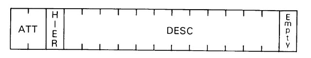
Every record in the text subfile consists of three elements--an attribute code, a hierarchy code, and a descriptor (fig. l0).
A text subfile record format of (I10, I5, 58A1, 8X) was designed to be compatible with the standard binary representation of GIRAS files. Each logical text subfile entry consists of one GIRAS 80-character record.
|
Figure l0.--A GIRAS text record.
Included in the text subfile are records for general codes that provide labels or descriptors for the more general categories under which specific polygon codes come. Consider references made to Level I and Level II Land Use and Land Cover categories. A polygon coded as "l3" is known to be Industrial. The digit "l" indicates that it falls under a broader category of Urban and Built-up Land. General code records also appear in the text subfile to provide definitions for these more general categories. For the above example, a text subfile record with "l0" in the polygon code (ATT) field would have the descriptor Urban and Built-up Land. (The "0" is for positional purposes only and can be considered insignificant.)
The hierarchy code (HIER) indicates the degree of generality of a text subfile polygon code (classification level). Specifically, the hierarchy code is defined as the number of insignificant digits on the right-hand side of the polygon code. Our sample Land Use and Land Cover text subfile records would thus appear:
______l0____1URBAN AND BUILT-UP LAND
______l3____0INDUSTRIAL
The role of the hierarchy code is more appreciated when dealing with other classification schemes utilized by GIRAS that involve multiple levels.
Text subfile records are arranged in ascending order by polygon code. Consequently, more general codes precede general codes of greater detail, which in turn precede codes explicitly referenced in the file. This ordering can be considered an indentation-type structure, as illustrated in table 5 for a sample census unit subfile.
Special polygon codes are required where available codes are not suitable. The set of special codes used in GIRAS is defined at the end of the subfile, as also shown in table 5. Special polygon codes were intentionally assigned extreme values (greater than 2,000,000,000) to force them to the bottom of the text subfile.
The type of map stored in a GIRAS file has an impact on the nature of the text subfile. Land Use and Land Cover and Federal ownership maps reference classification schemes that are attribute in nature. That is, there are a relatively limited number of possible codes (37 for Land Use and Land Cover and 26 for Federal ownership), and many polygons may have the same codes. The text subfiles for these types of GIRAS files list text records for all codes in the classification scheme. Consequently, all Land Use and Land Cover text subfiles are identical, as are Federal ownership text subfiles.
Census unit files, political unit files, and hydrologic unit files, alternatively, utilize codes that serve as unique identifiers. Two polygons rarely have the same code. Furthermore, it would not be feasible to list all possible codes. Consequently, only codes explicitly referenced in the file (and respective general and special codes) are defined in these types of GIRAS text subfiles.
The text subfiles for State ownership maps are not processed because coding schemes vary from situation to situation.
The length of the text subfile is given by the LTX parameter in the GIRAS map header. LTX refers to the number of logical text subfile records (that is, polygon code definitions) and includes general and special polygon codes.
The final GIRAS subfile is the associated data subfile that allows the user to store information of his own that pertains to the file (for example, population information that pertains to a particular census map). A pointer (NAD) to this subfile provides a place in the map header subfile to store the number of records in the associated data file once it is created.
Table 5.--Sample text subfile for a Census County Subdivision GIRAS file
          42000000                          6PENNSYLVANIA
          42051000                          3FAYETTE COUNTY
          4205l095                          0LURERENE
          42059000                          3GREEN COUNTY
          42059005                          0ALEPPO
         .
         .
         .
         .
          42059l27                          0WAYNE
          42059l30                          0WHITELEY
          54000000                          6WEST VIRGINIA
          5400l000                          3BARBOUR COUNTY
          5400l005                          0BAKER
          5400l0l5                          0ELK
          5400l025                          0PHILIPPI
         .
         .
         .
        l628000000                          6PITTSBURGH
        l628732000                          2WASHINGTON
        l628732000                          0WASHINGTON
        l628762000                          2WASHINGTON
        l628762000                          0WASHINGTON
         .
         .
         .
        l900000000                          6WHEELING
        l900020l00                          2MARSHALL
        l900020l00                          0MARSHALL
        l900020200                          2MARSHALL
        l900020200                          0MARSHALL
         .
         .
         .
        l900020900                          0..........
        2000000000                          9SPECIAL CODES
        2000000100                          2AREA UNDEFINED BY CODING SCHEME
        2000000l0l                          0LAND AREA UNDEFINED BY CODING
                                            SCHEME
        2000000l02                          0WATER AREA UNDEFINED BY CODING
                                            SCHEME
        2000000200                          2UNMAPPED AREA
        200000020l                          0UNMAPPED U.S. AREA
        2000000202                          0UNMAPPED NON-U.S. AREA
Digital data from all the overlays of a given quadrangle also are combined in a raster or grid-cell format as a Composite Theme Grid (CTG) file.
CTG files are sequential and consist of fixed-length logical records, and with the exception of header records, all records are of identical internal format, one grid cell per logical record. The grid cells are actually a regular point sample. The attribute codes at the center point of each cell are recorded from each overlay. The points are oriented to the UTM projection and are usually spaced 200 m apart in both east-west and north-south directions. The cell records are first ordered in the file by row from north to south, then within each row, by column west to east.
A character-formatted (usually ASCII) CTG file consists of fixed-length 80-character (card-image) logical records. There are two parts to the CTG file, first a header then cell records. All records, except the last header record with one text field, consist of fixed-length integer fields; each integer is coded as digits with leading blanks (i.e., right-justified). The first five logical records of the file comprise the CTG map header. The header is followed by cell records, one grid cell per 80-character logical record.
In some cases a CTG file may be released without the map header contained in the file. In this case all records in the file are individual grid cell records, and the header information is supplied as a printed listing.
Record 1:
Bytes 1-10 = Number of rows;
11-20 = Total number of cells x 2;
21-30 = Number of columns;
31-35 = Meaningless field;
36-40 = Cell size (width and length) in meters;
41-45 = Number of overlays merged;
46-50 = Map type code (see below);
51-55 = Projection zone number;
56-60 = Map projection code (should be
"1" for UTM);
61-70 = Scale of a plot at one mil per cell
width; and
71-80 = Source date of the land use overlay.
Record 2:
Bytes 1-5 = Minimum column index;
6-10 = Minimum row index;
11-15 = Maximum column index;
16-20 = Maximum row index;
21-25 = Column index for SW control point;
26-30 = Row index for SW control point;
31-35 = Column index for NW control point;
36-40 = Row index for NW control point;
41-45 = Column index for NC control point;
46-50 = Row index for NC control point;
51-55 = Column index for NE control point;
56-60 = Row index for NE control point;
61-65 = Column index for SE control point;
66-70 = Row index for SE control point;
71-75 = Column index for SC control point; and
76-80 = Row index for SC control point.
Record 3:
Bytes 1-10 = Latitude of SW control point;
11-20 = Longitude of SW control point;
21-30 = Latitude of NW control point;
31-40 = Longitude of NW control point;
41-50 = Latitude of NC control point;
51-60 = Longitude of NC control point;
61-70 = Latitude of NE control point; and
71-80 = Longitude of NE control point.
Record 4:
Bytes 1-10 = Latitude of SE control point;
11-20 = Longitude of SE control point;
21-30 = Latitude of SC control point;
31-40 = Longitude of SC control point;
41-50 = UTM Easting value of west edge of
cells;
51-60 = UTM Northing value of north edge of
cells;
61-70 = File creation date (a Julian date); and
71-80 = Meaningless field.
Record 5:
Bytes 1-64 = Title (text characters); and
65-80 = Blank.
Some further explanation is needed for some of the elements in the CTG map header:
| The map type code (in bytes 46-50 of the first record) indicates which
overlays have been included in the CTG data file. The code is formed by the addition (in
base 10) of the separate GIRAS map type codes for each of the overlays: 01 = Land Use
and Land Cover; |
| The UTM Easting and Northing values given in the fourth record (bytes
41-60) are in whole meters and are values for the west and north edges of the cells,
rather than the center point of the first (northwest corner) cell. The Easting and
Northing values for a given cell may be calculated thus: Easting = (XORG-CW/2) + (column
index)*CW where XORG and YORG are the Easting and Northing values in bytes 41-60 of the fourth
header record, and CW is the cell width in bytes 36-40 of the first header record. |
| The control points usually define the 1° x 2° (for 1:250,000-scale base maps) or 30' x 1° (for 1:100,000-scale base maps) quadrangle on which the overlay data are based. The latitude and longitude values are given as positive integers of the form DDDMMSS, where DDD is degrees, MM is minutes, and SS is seconds. West longitude values are given as positive numbers, increasing in value from east to west. The row and column values given for the control points are the indices for the cell whose center point is closest to the true position of the control point. |
Each grid cell logical record of a standard character-formatted CTG data file is 80 characters in length and consists of nine decimal integers, right justified (with leading blanks) within fixed-length fields:
| Bytes 1-3 = | UTM zone number (this value should be the same in every record of a given CTG file); the first byte will always be a blank for zones in the northern hemisphere; |
| 4-11 = | UTM Easting value, in whole meters, for the sample point of the cell; |
| 12-19 = | UTM Northing value, in whole meters, for the sample point of the cell; |
| 20 = | Blank; |
| 21-30 = | Land Use and Land Cover attribute code; |
| 31-40 = | Political unit (FIPS State/county) code; |
| 41-50 = | USGS hydrologic unit code; |
| 51-60 = | Census county subdivision or SMSA tract code; |
| 61-70 = | Federal land ownership agency code; and |
| 71-80 = | State land ownership code. |
If a given overlay category has not been included within the file, the codes for that category will be zero (0). Since some misregistration of map overlays occurs, some of the cells along the edges of the 1:250,000- or 1:100,000-scale quadrangle may have codes for some overlays, but not others (the "other" code(s) will be zero). The standard character CTG data file will have only those cell records for which at least one of the categories is coded. This means that, since the 1:250,000- and 1:100,000-scale quadrangles do not form perfect rectangles in the UTM projection (lines of latitude curve and lines of longitude converge), a variable number of cell records will exist for any given row or column.
Each logical record of a binary CTG file is either 32 or 52 bytes in length. A record consists of eight 32-bit (4-byte) binary integers in the following order:
| Bytes 1-4 = | Row index, where 1 is the index of the northern-most row and index numbers increase by one for each row moving south (NOTE, due to a processing error, CTG files in which the State ownership is not coded will have all zero row index numbers; the row index is then a function of the sequential position of the record within the file); |
| 5-8 = | Column index, where 1 is the index of the western-most column and index numbers increase by one for each column moving east; |
| 9-12 = | Land Use and Land Cover code; |
| 13-16 = | Political unit code; |
| 17-20 = | Hydrologic unit code; |
| 21-24 = | Census county subdivision or SMSA tract code; |
| 25-28 = | Federal land ownership code; |
| 29-32 = | State land ownership code; and |
| 33-52 = | Null (binary zeros) field, if present. |
If a given overlay has not been digitized, the codes for that overlay will all be zero. To be sure that a regular grid of cells (forming a UTM rectangle) covers the entire base map quadrangle, a "buffer zone" of cells with all zero attributes has been included in the binary CTG data file.
The CTG map header associated with a binary CTG data file is stored in a physically separate sequential file. The header consists of six, 32-byte logical records. For the first four records, each 32-byte binary record is equivalent to an 80-character CTG map header card image; each integer in a 5-digit character field is stored in a 2-byte binary integer field, and each integer in a 10-digit character field is stored in a 4-byte binary integer field. The fifth card-image header record (with text data) is represented as the fifth and sixth 32-byte binary records with EBCDIC coded characters (the last 16 characters of the card-image record are always blank).
Anderson, J.R., Hardy, E.E., Roach, J.T., and Witmer, R.E., l976, A Land Use and Land Cover classification system for use with remote sensor data: U.S. Geological Survey Professional Paper 964, 28 p.
Mitchell, W.B., Guptill, S.C., Anderson, K.E., Fegeas, R.G., and Hallam, C.A., l977, GIRAS--A geographic information retrieval and analysis system for handling Land Use and Land Cover data: U.S. Geological Survey Professional Paper l059, l6 p.
U.S. Bureau of the Census, l972a, Census tracts--1970 census of population and housing: U.S. Bureau of the Census Final Reports PHC(1)-1 through PHC(1)-241. (One volume for each SMSA.)
______1972b, County and city data book, 1972: U.S. Bureau of the Census, 1020 p.
______1972c, Geographic identification code scheme--1970 census of population and housing: U.S. Bureau of the Census Final Reports PHC(R)-3 Northeast Region, North Central Region, South Region, and West Region. (One volume for each region.)
______1983a, Census tracts--1980 census of population and housing: U.S. Bureau of the Census Final Maps PHC80-2-58 through PHC80-2-380. (One map for each SMSA.)
______1983b, County and city data book, 1983: U.S. Bureau of the Census, 1060 p.
______1983c, 1980 County subdivision maps: U.S. Bureau of the Census. (One map for each State.)
______1983d, Geographic identification code scheme--1980 census of population and housing: U.S. Bureau of the Census Final Report PHC80-R5.
U.S. Geological Survey, 1982, Codes for the identification of hydrologic units in the United States and the Caribbean outlying areas: U.S. Geological Survey Circular 878-A.
APPENDIX A.--Listing of Sample GIRAS Map Header Data
TITLE: KEY WEST, FL 1:250000 QUAD POLITICAL
FILE CREATION DATE: 83004   TIME 21:56
MAP TYPE:    2    PROJECTION:  1    SCALE 1: 393700    SOURCE DATE: 1972
NUMBERS OF FILE ELEMENTS:
           ARC       COORD-  POLYGON    FAP      TEXT   ASS. DATA  TITLE
SECTIONS  RECORDS   INATES   RECORDS  ELEMENTS  RECORDS  RECORDS   CHARS
    1       27       4350     24        71         0        0       50
DUPLICATE POINT TOLERANCE =  3      MINIMUM ARC LENGTH =  10
MINIMUM X = 8130  MINIMUM Y = 5403  MAXIMUM X = 28478  MAXIMUM Y = 16523
   CONTROL POINT INFORMATION:
                  LONGITUDE          LATITUDE         X          Y
SOUTH-WEST         821000             240000        8130       5462
NORTH-WEST         821000             250000        8227      16523
NORTH-CENTRAL      811000             250000       18318      16479
NORTH-EAST         801000             250000       28410      16510
SOUTH-EAST         801000             240000       28478       5429
SOUTH-CENTRAL      811000             240000       18304       5409
SECTION HEADER INFORMATION FOR SECTION  1:
NUMBER OF ARCS  =      27          NUMBER OF COORDINATES =   4350
NUMBER OF POLYGONS =   24          NUMBER OF FAP ELEMENTS =    71
NUMBER OF NODES  =     25          CURRENT MARK STATUS  =      50
MINIMUM X = 8130  MINIMUM Y = 5403  MAXIMUM X = 28478  MAXIMUM Y =16523
APPENDIX B.--Sample Character-Formatted GIRAS Data File
        27      4350        24    3   10    1    2    0    1    393700      1972
 8130 54032847816523 8130 5462 8227165231831816479284101651028478 542918304 5409
    240000    821000    250000    821000    250000    811000    250000    801000
    240000    801000    240000    811000    0   50   71          83004
KEY WEST, FL 1:250000 QUAD POLITICAL
    1   27 4350   24   71   50 8130 54032847816523   25
    1   10    0   23         02000000102 8182116592458916523     21225    1    2
    2   14    0   20         0     1208724589164862471616487       127    2    3
    3   30    0   23         02000000102 8130 54032847816510     41299    3    4
    4   34    0    1         0     12087 818211638 818211659        22    4    1
    5  108   23    12000000102     12087 818211523 827411722       552    1    4
    6  280   23    22000000102     12087 838211527 885912073      2154    5    5
    7  320   23    32000000102     12087 976611290 987811402       356    6    6
    8  350   23    42000000102     1208710078112361019311273       263    7    7
    9  380    5   23     12087200000010210602112701070411513       570    8    8
   10  410   22   23     12087200000010210964116221101311672       162    9    9
   11  436   21   23     12087200000010210643120981069012165       186   10   10
   12  512    6   23     12087200000010212237123931270512673      1373   11   11
   13 2492   23    92000000102     1208711744114661767414298     26907   12   12
   14 2582   23    72000000102     1208713929131161432913491      1267   13   13
   15 2626   23    82000000102     1208714215137341434913830       402   14   14
   16 2690   23   102000000102     1208714972135821504613767       456   15   15
   17 2724   23   112000000102     1208716223139341628414020       237   16   16
   18 2842   23   122000000102     1208716544133171696813888      1647   17   17
   19 2892   23   132000000102     1208717027139081711414039       357   18   18
   20 2928   23   242000000102     1208717661139771771114056       210   19   19
   21 3544   23   142000000102     1208718748130262092314003      6399   20   20
   22 3568   23   152000000102     1208721085141062113614137       133   21   21
   23 3760   23   162000000102     1208721504142692214314730      2247   22   22
   24 3898   23   172000000102     1208722590147842312615459      2010   23   23
   25 3920   23   182000000102     1208722138157712218515819       154   24   24
   26 3952   23   192000000102     1208723379162652355416422       501   25   25
   27 4350   20   23     12087200000010223318153312472516487      4780    2    3
 818211659 822716523134751649218804164732458916487245891648724716164862471616486
284101651028478 542922551 540418227 540311066 5437 8130 5462 818211638 818211638
 818211659 818211659 819011671 819511687 819811696 822511722 823211722 823811721
 824011713 824011700 822111675 820711649 820511626 820411595 820511588 821511566
[ 265 records of the Coordinate Subfile are removed from this listing here ...]
24420160722447216106244991613224511161532453116189245461620324550162192455816234
24597162672460316283246321630724641163392465516358246801637224700163822470616395
2470116412247091642724720164332472516448247201645924717164672471616486
    1    2 818511656     12087      6117 818211523 827411722       574    0    0
    2    3 861911544     12087     54753 838211527 885912073      2154    0   23
    3    4 978011396     12087      8374 976611290 987811402       356    0   23
    4    51013311243     12087      317810078112361019311273       263    0   23
    5    61069911481     12087     1354610602112701070411513       570    0   23
    6    71254712605     12087     5691312237123931270512673      1373    0   23
    7    81415613366     12087     3678213929131161432913491      1267    0   23
    8    91423613802     12087      419914215137341434913830       402    0   23
    9   101175411653     12087   365911711744114661767414298     26907    0   23
   10   111502413589     12087      812014972135821504613767       456    0   23
   11   121624314017     12087      317816223139341628414020       237    0   23
   12   131678113799     12087    10720116544133171696813888      1647    0   23
   13   141710013914     12087      588717027139081711414039       357    0   23
   14   151975513330     12087    30062418748130262092314003      6399    0   23
   15   162110214111     12087      103421085141062113614137       133    0   23
   16   172179514396     12087     5627521504142692214314730      2247    0   23
   17   182310915186     12087     6600622590147842312615459      2010    0   23
   18   192216015774     12087      170822138157712218515819       154    0   23
   19   202349916271     12087     1585523379162652355416422       501    0   23
   20   222459616482     12087    18878023318153312472516487      4907    0    0
   21   231067312147     12087      226910643120981069012165       186    0   23
   22   241099211661     12087      163910964116221101311672       162    0   23
   23   7024724164802000000102 219786908 8130 54032847816523    115849   21    0
   24   711770613984     12087      201517661139771771114056       210    0   23
    5    4    6    7    8   -9  -12   14   15   13   16   17   18   19   21   22
   23   24   25   26    2  -27  -11  -10    3   -5    1   27    0   -6    0   -7
    0   -8    0    9    0   12    0  -14    0  -15    0  -13    0  -16    0  -17
    0  -18    0  -19    0  -21    0  -22    0  -23    0  -24    0  -25    0  -26
    0   11    0   10    0  -20   20[ END OF DATA ]
APPENDIX C.--Listing of CTG Map Header Data
COMPOSITE THEME GRID CHARACTER DATA OUTPUT:
C T G B T A   RUN:  JUNE 3, 1982     TIME 19:23:06
GRID CELL MAP HEADER INFORMATION:
TITLE: LAWRENCE, MO KS 1:250,000 QUAD LU PB CN HU FO SO
FILE CREATION DATE: 81084   TIME  0: 0
MAP TYPE:   77    PROJECTION:  1      SCALE 1:  7874016    MAP DATE: 1973
NUMBERS OF FILE ELEMENTS:
CATEGORIES    CELLS    ROWS    COLUMNS    ZONE    WEST & NORTH  EDGES:
                                         NUMBER    EASTING   NORTHING
     6       485368    575      884       15        236900    4321100
DUPLICATE POINT TOLERANCE =    0     CELL SIZE IN METERS =   200
MIN COL =     1    MIN ROW =     1     MAX COL =   884    MAX ROW =   575
   CONTROL POINT INFORMATION:
               LONGITUDE     LATITUDE     COL      ROW
SOUTH WEST       960000      380000       -1       557
NORTH WEST       960000      390000       17         2
NORTH EAST       940000      390000      883        21
SOUTH EAST       940000      380000      877       576
CHARACTERISTICS OF THE CHARACTER CTG FILE:
THE FILE CONTAINS ONLY GRID CELL (AND NO HEADER) RECORDS.
THE FILE CONSISTS OF 80 CHARACTER RECORDS, ONE GRID CELL PER RECORD.
UTM ZONE, EASTING, AND NORTHING VALUES ARE PART OF EACH CTG DATA RECORD AS THE
FIRST THREE INTEGERS, RIGHT JUSTIFIED IN BYTES 1-3, 4-11,AND 12-19.
BYTES 21-80 OF EACH RECORD CONTAIN THE USGS 10-DIGIT INTEGER CODES, RIGHT
JUSTIFIED WITHIN 10-BYTE FIELDS, FROM THE FOLLOWING OVERLAYS, IN ORDER:
LAND USE/LAND COVER, POLITICAL UNIT, HYDROLOGIC UNIT, CENSUS SUBDIVISION/TRACT,
FEDERAL LAND OWNERSHIP, AND STATE LAND OWNERSHIP.
ONLY RECORDS WITH AT LEAST ONE NON-ZERO ATTRIBUTE ARE PART OF THE FILE.
(A VARIABLE NUMBER OF RECORDS EXIST FOR A GIVEN ROW OR COLUMN.)
APPENDIX D.--Sample "Standard" Character-Formatted
                  CTG Data File (without header)
 15  240200 4321000         21         0         0         0         0         0
 15  240400 4321000         21         0         0         0         0         0
 15  240600 4321000         21         0         0         0         0         0
 15  240800 4321000         21         0         0         0         0         0
 15  241000 4321000         21         0         0         0         0         0
 15  241200 4321000         21         0         0         0         0         0
 15  240200 4320800         21     20197  10270102         0      2099      2099
 15  240400 4320800         21     20197  10270102         0      2099      2099
 15  240600 4320800         21     20197  10270102         0         0      2099
 15  240800 4320800         21     20197  10270102         0         0      2099
 15  241000 4320800         21     20197  10270102         0         0      2099
 15  241200 4320800         21     20197  10270102         0         0      2099
 15  241400 4320800         21     20197  10270102         0         0      2099
 15  241600 4320800         21         0         0         0         0      2099
 15  241800 4320800         21         0         0         0         0      2099
 15  242000 4320800         21         0         0         0         0      2099
 15  242200 4320800         21         0         0         0         0         0
 15  242400 4320800         31         0         0         0         0         0
 15  242600 4320800         31         0         0         0         0         0
 15  242800 4320800         31         0         0         0         0         0
 15  243000 4320800         31         0         0         0         0         0
 15  243200 4320800         31         0         0         0         0         0
 15  243400 4320800         31         0         0         0         0         0
 15  243600 4320800         31         0         0         0         0         0
 15  243800 4320800         31         0         0         0         0         0
 15  244000 4320800         31         0         0         0         0         0
 15  244200 4320800         31         0         0         0         0         0
 15  244400 4320800         31         0         0         0         0         0
 15  244600 4320800         31         0         0         0         0         0
 15  244800 4320800         31         0         0         0         0         0
 15  245000 4320800         31         0         0         0         0         0
 15  245200 4320800         31         0         0         0         0         0
 15  245400 4320800         31         0         0         0         0         0
 15  245600 4320800         31         0         0         0         0         0
 15  245800 4320800         31         0         0         0         0         0
 15  246000 4320800         31         0         0         0         0         0
 15  246200 4320800         31         0         0         0         0         0
 15  246400 4320800         31         0         0         0         0         0
 15  246600 4320800         21         0         0         0         0         0
 15  246800 4320800         21         0         0         0         0         0
 15  247000 4320800         21         0         0         0         0         0
 15  247200 4320800         21         0         0         0         0         0
 15  247400 4320800         21         0         0         0         0         0
 15  247600 4320800         21         0         0         0         0         0
 15  247800 4320800         21         0         0         0         0         0
 15  248000 4320800         21         0         0         0         0         0
 15  248200 4320800         21         0         0         0         0         0
 15  240200 4320600         21     20197  10270102  20197025      2099      2099
 15  240400 4320600         21     20197  10270102  20197025      2099      2099
 15  240600 4320600         21     20197  10270102  20197025      2099      2099
 15  240800 4320600         21     20197  10270102  20197025      2099      2099
 15  241000 4320600         21     20197  10270102  20197025      2099      2099
[ etc. ... ]